Bluetooth Low Energy Test Setup Configuration
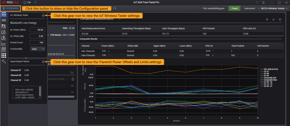
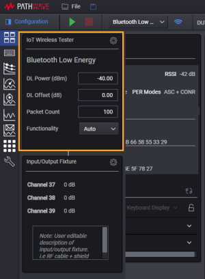
Use the Configuration panel to configure the global radio settings such as downlink power, downlink offset, and the packet count. This configuration panel consists of IoT Wireless Tester and Input/Output Fixture settings. Click the gear icons as indicated below to show the IoT Wireless Tester and Input/Output Fixture settings in a separate window.

| Global Radio Settings | Settings | Description |
|---|---|---|
|
|
Downlink (DL) Power |
Set the downlink power of X8721A. Enter the desired value from (-100 dBm + DL Offset) to (-25 dBm + DL Offset). |
| Downlink (DL) Offset | Set the offset value for the downlink power. |
|
| Packet Count |
Set the total number of packets ranging from 5 to 65,535 to calculate Packet Error Rate (PER). |
|
| Functionality |
Select the mode of PER measurement supported by the DUT from the drop-down list. The available options are as follows:
The default selection is set to Auto and the X8721A will scan for the supported PER modes. |
IoT Wireless Tester Settings
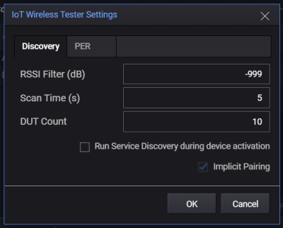
This is the settings dialog to edit the measurement settings according to the tabs shown below.

| Tabs | Settings | Description |
|---|---|---|
| Discovery | RSSI Filter (dBm) |
Set the threshold value of Received Signal Strength Indicator (RSSI) to filter the devices detected. Using the default value of -100 dB, the software will only display devices with RSSI values higher than -100 dB. |
| Scan Time (s) | Set the duration from 1 to 60 seconds for the X8721A to scan and discover devices. | |
| DUT Count | Set the maximum number of devices (1 to 4) to return during the discovery stage. | |
| Run Service Discovery during device activation | Select this check box to allow the software to discover services during device activation. | |
| Implicit Pairing | When this check box is selected, the software will use a previously stored Long Term Key to skip the pairing stage and directly Bond. The test step will prompt an error if the Long Term Key (stored on X8721A) does not match that of the LTK stored on the DUT indicating that a new pairing event is required to bond the device to the X8721A. | |
| PER | Packet Count |
Set the number of packets to test for PER. |
| Maximum Advertising Interval |
Set the maximum advertising interval per packet. |
|
| Limit (%) | Set the upper PER limit to indicate the Pass or Fail status. For example, results that exceed the PER limit set at 10% will be reported as Fail. | |
| Early Fail |
Enabling this will stop the measurement as soon as too many packets fail. For example, using a PER limit of 20% and a packet count of 10, PER measurement will stop immediately after the third failed packet. Using a PER limit at 20% and packet count of 10 as an example, the measurement will stop immediately when there are two failed received packets out of the 10 packets. |
|
|
PER
|
PHY |
Choose the variant of Physical Layer (PHY) such as LE1M, LE2M, CodedS2 and CodedS8 that is supported by your DUT. Generally, Bluetooth® 4.2 devices only support LE1M while certain Bluetooth® 5 devices can support all four options. |
|
Method |
Set one method out of the 10 options listed in the drop-down list. Based on the selected method, the X8721A will scan and request these information from the detected devices. |
|
| Channels |
Select the data channels (in pairs). You may select up to six pairs (maximum). Once you have selected the channels, go to Input/Output Fixture section to set the desired limit and offset values. Note: The offsets are interpolated between channels. |
Transmit Power Offsets and Limits
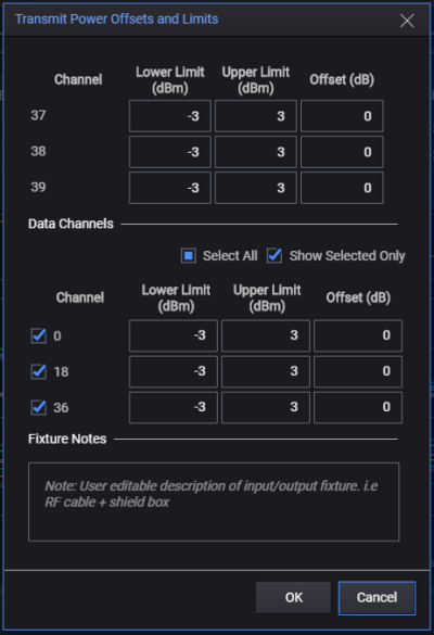
This panel displays the settings of the system offsets for a single device measurement or dynamic multi-device measurement.

| Settings | Description |
|---|---|
| Lower and Upper Limit (dBm) |
Set the limits in dBm. |
| System Offset (dB) |
Enter the amount by which signal strength changes between the DUT and the RFIO port. This will usually be a negative number. When you are using the Connect Request mode, the offsets are interpolated between channels. For more information, refer to the note below. |
| Fixture Notes | This is a description box where you can input your notes about input/output fixture. |
Offsets
Within this document the term “Offset” is used to describe the net gain or loss between the RF I/O connector of the X8721A and the Device Under Test (DUT). A gain is entered as a positive number and a loss is entered as a negative number. In a typical setup the network between the RF I/O port and the DUT might be a cable or a cable and an antenna coupler. In either case the net gain or loss (usually a loss) will be the number entered into the Offset parameter.
Measuring and Calculating Offsets
The topic of how to calculate these offsets is beyond the scope of this document. In general, a methodology needs to be adopted that allows for sufficient accuracy in measuring the offsets. In the case of a cable, it could be directly measured using a vector network analyzer (as an example). When measuring offsets of an antenna coupler network this can be a bit more complicated, but there are techniques that offer reasonable levels of accuracy/precision with limited complexity.
Example
Assume that you want the RF power of -40 dBm to arrive at the DUT. In an ideal, lossless environment (which does not exist), you would set the DL Power to -40 and the DL Offset to 0 to achieve that. However, you have 6 dB of loss along the path from the DUT antenna to the RFIO connector of the X8721A. In this case, you would set the offset to -6 dB for the system firmware to automatically add it to the power and send an RF signal at -34 dB, so that the signal arriving at the DUT will be -40. For the X8721A cannot send power above -28 dB, the DL Offset cannot be lower than -4 to achieve a DL Power of -32 dBm.
