Run the Multi-DUT Test
Before you test your DUTs, you must use reference DUTs to characterize path losses at different positions. You may use an antenna coupler or a far field antenna within the shield box. Each position in the shield box has its own path loss.
This section explains a general guideline to use the Multi-DUT Test to characterize the path loss and later to use the calculated offset values when you perform the measurements on the actual DUT(s). The Multi-DUT Test is a measurement that is only available in IoT Soft Front Panel Pro.
Here are a few items to take note:
- The reference device (up to four) must have a known transmit power or power level. This method will work better when you have a more accurate power level to work with. You will need this information to calculate System Offset later.
- Identify the suitable location and pattern of arranging the DUT(s) within the shield box. It is possible that choice of location and pattern may introduce a significant amount of error.
- To minimize the impact of positioning errors, you will need to rotate the DUT(s) at least once to collect the path loss offset data for each location. You will then apply the average of the collected data to compensate for the path loss.
- Positioning errors can significantly impact measurement repeatability, so consider a mechanical fixture to improve positioning repeatability.
Device-Under-Test (DUT) Positioning
The arrangement and orientation of DUTs will affect measurement accuracy. Experiment with different arrangement to find the optimal pattern. For a single DUT, place it at the center of the antenna loop.
Here are a few recommendations on how to place your DUTs based on the use of four CC2650 TI SensorTags in the X8763A small-sized shield box:
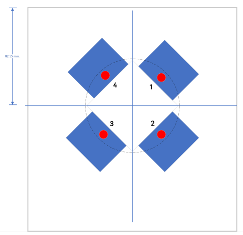
- The best performance was obtained when the DUTs are placed 45 degrees off X-axis (see the figure in the table below). With this arrangement, the DUTs are placed at almost equal distance and orientation with respect to the antenna coupler residing in the shield box.
- It is important to allow some space between the DUTs to minimize the loading effects between the antennas of the DUT. When the DUTs are placed too close, the antennas will interact with each other and deform the antenna radiation pattern and eventually affect the accuracy of the measurement.
- Placing the DUTs at a certain angle (45 degrees) off the x-axis will allow the DUTs to be placed far away from the walls of the shield box. This will reduce the distortion in the antenna radiation pattern.
Once you have determined the positions, you may use a fixture to indicate the fixed positions for all the four DUTs on the grid plate of the shield box.
| Up to four devices |
|---|
|
|
|
This is the recommended placement and orientation based on the use of four CC2650 TI SensorTags (where the red dots indicate the location of antenna) as reference DUTs to fit a small-sized shield box. |
Path Loss Measurement Procedure
- Position the four DUT(s) in the shield box as shown in the table above and mark the fixed positions on the grid plate of the shield box or you may label on the physical DUTs.
- If not already launched, launch IoT Soft Front Panel on PathWave Desktop Edition.
-
Click the Multi-DUT icon (
 ) from the side menu to see the expanded view. To set the appropriate controls for the Multi-DUT Composite Test, click the Configuration panel followed by the gear icon as shown below.
 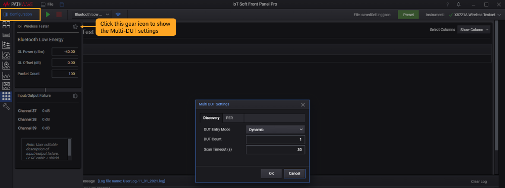 NOTE
NOTEIn general, here are the settings that you will need to configure. These settings are as described in Multi-DUT Settings.
- In the Discovery tab:
- Select the desired Entry Mode to be Dynamic or User Entry. The Dynamic mode allow the X8721A to scan and populate a list of detected devices. Select the User Entry option to enter individual MAC addresses or use the Select DUTs option to select any of the detected devices.
- Set the Device Count to match the number of DUTs placed in the shield box.
- In the PER tab, you may modify the settings such as Method, Trigger, Packet Count, Packet Limit to narrow down the list of devices detected.
- In the Discovery tab:
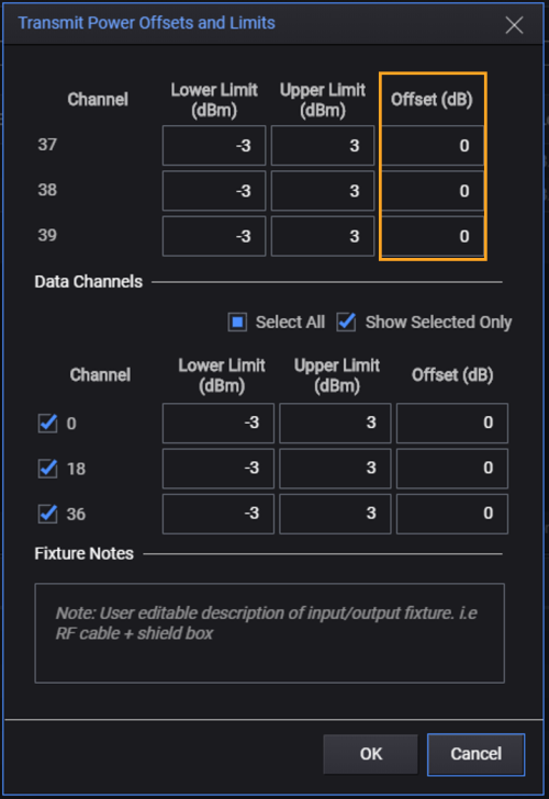
- Before you run the test, open the Configuration panel > Input/Output settings dialog to verify the value of System Offset. When you are characterizing the path loss, the channel offsets should be set to zero.
- Click Run (
 ) to execute the Multi-DUT test. Observe the progress spinner. If you wish to stop the data acquisition, click Stop (
 ).
). -
Upon the completion of the test, record your results and include the known power of the reference DUTs in the template provided below. This is a template that you can use and duplicate according to the number of times you intend to run the test plan. You will use these values to calculate the offset values later.
Position of DUT MAC Address (FF:FF:FF:FF) Measured Tx Power Tx Power of reference DUT (dBm) Ch 37 Ch 38 Ch 39 Ch 37 Ch 38 Ch 39 1
2
3
4
-
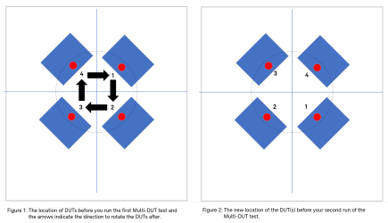
Rotate the DUT(s) to the next position in a clockwise direction as indicated in Figure 1. When the reference DUT(s) are placed according to Figure 2, repeat step 5 and 6 to run the Multi-DUT test and record the measured power values in the table.
NOTETo characterize path loss at each position, you must rotate the reference DUT(s) before you run the next Multi-DUT Test. The number of rotations will depend on the number of DUTs and test positions.
Based on this four-DUT configuration, you will need to rotate the DUTs and perform the same BLE Multi-DUT Signaling Test plan for a total of four times until the reference DUTs return to their locations in Figure 1.
At this point, you should have four sets of measured data after completing four runs of Multi-DUT Test. You will use the collected measured data to calculate the system offsets (path loss) for all the four DUTs at each positions in the next section.
Here is an example of the completed table in step 6 after running the test for four times until the reference DUTs return to their locations. For this example, the power of the reference DUT is +5 dBm.
| Position of DUT (first run) | MAC address (FF:FF:FF:FF) | Measured Tx Power (dBm) | Tx Power of reference DUT (dBm) | ||||
|---|---|---|---|---|---|---|---|
| Ch 37 | Ch 38 | Ch 39 | Ch 37 | Ch 38 | Ch 39 | ||
| 1 | 80:6f:b0:ef:d7:a3 | -17.82 | -18.62 | -20.47 | 5 | 5 | 5 |
| 2 | 80:6f:b0:f0:11:b6 | -20.38 | -22.75 | -21.21 | 5 | 5 | 5 |
| 3 | 18:04:ed:bf:0f:4c | -20.07 | -21.58 | -25.37 | 5 | 5 | 5 |
| 4 | 80:6f:b0:ef:da:7b | -24.16 | -24.56 | -25.01 | 5 | 5 | 5 |
| Position of DUT (second run) |
|
|
|
|
|
|
|
| 1 | 80:6f:b0:ef:da:7b | -20.26 | -21.04 | -20.48 | 5 | 5 | 5 |
| 2 | 80:6f:b0:ef:d7:a3 | -22.67 | -23.27 | -22.65 | 5 | 5 | 5 |
| 3 | 80:6f:b0:f0:11:b6 | -22.56 | -23.93 | -27.9 | 5 | 5 | 5 |
| 4 | 18:04:ed:bf:0f:4c | -19.04 | -20.38 | -21.82 | 5 | 5 | 5 |
| Position of DUT (third run) |
|
|
|
|
|
|
|
| 1 | 18:04:ed:bf:0f:4c | -19.11 | -20.03 | -22.1 | 5 | 5 | 5 |
| 2 | 80:6f:b0:ef:da:7b | -22.53 | -24 | -24.07 | 5 | 5 | 5 |
| 3 | 80:6f:b0:ef:d7:a3 | -20.64 | -22.17 | -25.23 | 5 | 5 | 5 |
| 4 | 80:6f:b0:f0:11:b6 | -19.64 | -20.15 | -20.29 | 5 | 5 | 5 |
| Position of DUT (fourth run) |
|
|
|
|
|
|
|
| 1 | 80:6f:b0:f0:11:b6 | -20.77 | -21.37 | -23.19 | 5 | 5 | 5 |
| 2 | 18:04:ed:bf:0f:4c | -20.07 | -21.02 | -21.12 | 5 | 5 | 5 |
| 3 | 80:6f:b0:ef:da:7b | -20.66 | -22.31 | -22.96 | 5 | 5 | 5 |
| 4 | 80:6f:b0:ef:d7:a3 | -20.77 | -22.13 | -24.41 | 5 | 5 | 5 |
Calculating System Offsets (Path Loss)
With the collected data that represents the reference DUTs in each of the positions, you can now calculate the average System Offset for each positions with the formula below. It is important to know the transmit power of the reference DUTs to calculate the offsets.
Use this formula to calculate the System Offset:
System Offset = Measured Tx power - Known power of reference DUT
For example, if the measured power obtained is -10 dBm and the known output power from reference DUT is 0 dBm, the System Offset can be calculated as -10 - 0 = -10 dB.
Proceed to calculate the average System Offset for each position. Here is an example of the calculated pass loss values based on the completed table in step 6.
| Position of DUTs (first run) | MAC address (FF:FF:FF:FF) | Path loss (dB) | ||
|---|---|---|---|---|
| Ch 37 | Ch 38 | Ch 39 | ||
| 1 | 80:6f:b0:ef:d7:a3 | -22.82 | -23.62 | -25.47 |
| 2 | 80:6f:b0:f0:11:b6 | -25.38 | -27.75 | -26.21 |
| 3 | 18:04:ed:bf:0f:4c | -25.07 | -26.58 | -30.37 |
| 4 | 80:6f:b0:ef:da:7b | -29.16 | -29.56 | -30.01 |
| Position of DUTs (second run) |
|
|
|
|
| 1 | 80:6f:b0:ef:da:7b | -25.26 | -26.04 | -25.48 |
| 2 | 80:6f:b0:ef:d7:a3 | -27.67 | -28.27 | -27.65 |
| 3 | 80:6f:b0:f0:11:b6 | -27.56 | -28.93 | -32.90 |
| 4 | 18:04:ed:bf:0f:4c | -24.04 | -25.38 | -26.82 |
| Position of DUTs (third run) |
|
|
|
|
| 1 | 18:04:ed:bf:0f:4c | -24.11 | -25.03 | -27.10 |
| 2 | 80:6f:b0:ef:da:7b | -27.53 | -29 | -29.07 |
| 3 | 80:6f:b0:ef:d7:a3 | -25.64 | -27.17 | -30.23 |
| 4 | 80:6f:b0:f0:11:b6 | -24.64 | -25.15 | -25.29 |
| Position of DUTs (fourth run) |
|
|
|
|
| 1 | 80:6f:b0:f0:11:b6 | -25.77 | -26.37 | -28.19 |
| 2 | 18:04:ed:bf:0f:4c | -25.07 | -26.02 | -26.12 |
| 3 | 80:6f:b0:ef:da:7b | -25.66 | -27.31 | -27.96 |
| 4 | 80:6f:b0:ef:d7:a3 | -25.77 | -27.13 | -29.41 |
Next, calculate the average path loss for all the four runs as you will use the average performance (of the four DUTs) at each of the locations. Once again, the table is an example of the computed values.
| Position | Average Path loss (dB) | ||
|---|---|---|---|
| Ch 37 | Ch 38 | Ch 39 | |
| 1 | -24.49 | -25.27 | -26.56 |
| 2 | -26.41 | -27.76 | -27.26 |
| 3 | -25.98 | -27.50 | -30.37 |
| 4 | -25.90 | -26.81 | -27.88 |
Apply System Offsets and Validate the Measurement Results
To validate the system offsets, update the System Offsets value in the Input/Output Fixture settings (as described in Bluetooth Low Energy Test Setup Configuration) and measure the reference DUTs in all of the positions based on the steps in Path Loss Measurement Procedure section.
A general guideline to determine if the validation results are acceptable are as follows:
- Verify that the measured TX power matches the DUT's known output power (+5 dBm in this example). You must judge what variation is acceptable based on the expected performance and test margin.
- In the case when the results do not match the known power of the DUT, verify that the positions marked one to four did not change. Ensure that you have been placed the DUTs at the same position with the correct orientation consistently.
Upon validation, you may run the same Multi-DUT Test to test the actual DUTs based on the established choice of location, pattern, and system offset values.
To perform other measurements using the IoT Soft Front Panel, go to Run the Measurement page.