Channels
In the Channels section shown below, configure the following settings and set the voltage and current limit according to the choice of SMU modules installed.
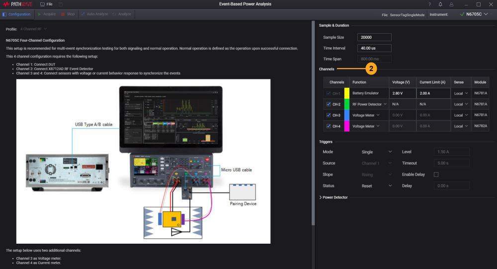
Function
The settings for Channel 1 is fixed as Battery Emulator while you can select any one of the four modules below for Channel 2:
- RF Power Detector
- Voltage meter
- Current meter
- 2-Q Power Supply
Select any two of the following modules for Channel 3 and 4
- Current meter
- Voltage meter
- 2-Q Power Supply
-
Selecting the 2-Q Power Supply module will require user to set a voltage in order to measure current. The current measured could be a positive or negative value.
- Clear the check boxes for the channels that are not in use to disable the KS833A2A software settings.
-
Channel 1 as the Battery Emulator module sets constant voltage and measure current. The current limit functions to protect the DUT and act as measurement range.
Local and Remote Sense
The power analyzer includes built-in relays that connect or disconnect the sense terminals from their corresponding output terminals. As shipped, the sense terminals are internally connected to the output terminals. This is referred to as Local sensing.
4-wire, or remote sensing improves the voltage regulation at the load by monitoring the voltage at the load rather than at the output terminals. This automatically compensates for the voltage drop in the load leads, which is especially useful for CV operation with load impedances that vary or have significant lead resistance. Because remote sensing is independent of other power analyzer functions, it can be used regardless of how the instrument is programmed. Remote sensing has no effect during CC operation.
The following figures illustrate load connections using local sensing (A), and 4-wire remote sensing (B). When the 4-wire indicator above the sense terminals is on, it indicates that the sense terminals must be connected to the load.
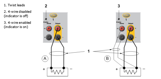
For more information, refer to the 4-Wire Sense Connections in N6705C DC Power Analyzer User's Guide.
List of Supported SMU Modules
Based on the choice of SMU modules installed in N6705C, ensure that the set voltage and current limit falls within the range below along with the supported modes and channels.
Event-based Power Analysis version 2.0 with KS833A2A license
| Modules | Voltage Range (V) | Current Limit (A) | Modes | Can be used on Channel |
|---|---|---|---|---|
| N6781A |
0 to 6.12 6.13 to 20.4 |
0 to 3.06 0 to 1.02 |
VM, AM and 2-QPS | 1, 2, 3, and 4 |
| N6782A * | 1, 2, 3, and 4 | |||
| N6784A * | 2, 3, and 4 | |||
|
N6785A (Double-wide power module) |
0 to 6.12 6.13 to 20.4 10.3 to 15.3 15.4 to 20.4 |
0 to 8.16 0 to 6.83 0 to 5.10 0 to 4.08 |
1 or 3 | |
|
N6786A * (Double-wide power module) |
1 or 3 | |||
| N6791A | 0 to 61.2 | 0 to 20.4 | VM and AM | 2, 3, and 4 |
|
N6792A * (Double-wide power module) |
0 to 61.2 | 0 to 40.8 | 3 only |
- * The N6782A, N6784A, N6786A, N6791A and N6792A are only supported in Event-based Power Analysis version 1.1.03079.0 or above with KS833A2A license.
- Double-wide power modules such as N6785A, N6786A and N6792A have a higher capacity and will occupy two slots when installed in the N6705C. They can only be installed on Channel 1 or 3. When installed in Channel 1 (Battery Emulator), Channel 2 (Power Detector) will automatically disable and you will not be able to use Channel 2 to monitor RF events.
-
It is not recommended to install the N6784A module in Channel 1 as it does not support the seamless auto range (SMR) feature. The software will automatically disconnect when N6784A is installed in Channel 1.
-
It is not recommended to install the N6791A and N6792A modules in Channel 1 as they do not support the power supply function.
Next
According to your test case and requirements, configure the following settings: