Triggers
This setting sets the trigger point to start or stop tabulating the results. There are three modes available and the settings for each mode are as described in the table below.
When selecting the correct capture mode to measure your IoT device using Event-based Power Analysis application, you will need to take note of the advantages and limitations of each Trigger mode as described below.
The minimum sampling period for Continuous Mode is 102.4uS for every channel (409.6uS for four active channels). In continuous sampling mode, the N6705C hardware can internally sample the data a rate of about 20uS while keeping the average. This data is then resampled to the requested sampling period (that is 102.4uS). The purpose of down sampling is to enable the system to stream data without under or over running its circular buffer.
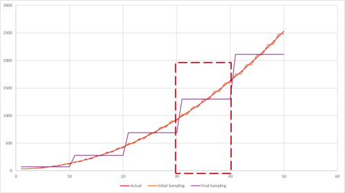
Since the N6705C is measuring the average current (or voltage) over the sampling period the accuracy of the measurement can be preserved when the measured data is down sampled. Effectively the N6705C re-averages the measured data over the new sampling period. If one were to think of the measured current (or voltage) vs time as the area under the curve then by resampling we are able to preserve the accuracy of the original sampled data (measured at a faster rate). In the example below the red trace is the “actual” waveform, the orange the initial sampling, and purple the final sampling. If we look at any period of time that is common to all three sampling rates the sum of the data (area under the curve) will be the same. In this example if we look at the area under the curve from 31 to 40 we see that they are the same at 13005 for all three curves.
Due to the sampling system of the N6705C hardware and its attributes, certain detail may be lost due to the under sampling of the events. While the average voltage or current remains unaffected, the peak measurements will be affected. Since the estimated battery life is calculated based on the value of average current, the results will still be reasonably accurate and useful when using Continuous Mode.
In single mode, the sampling memory is used to capture one chunk of data. Similar to Continuous mode, the hardware captures the data and writes it to the internal memory before making it available for transfer to a host PC. As such the sampling rate can be much faster in this mode. In fact, the minimum sampling period for one channel in Single Trigger Mode is 5.12uS (20.48uS for four channels). Similar to the continuous mode, the single mode stores the average current during acquisition and then resamples it to the maximum sampling rate prior to storage in the sampling memory (that is 5.12uS for 1 channel). This means that there are no statistically difference between the average results from Single or Continuous Modes.
With these differences in mind, you can start to understand how to more fully utilize the software using the particular advantages and disadvantages of single and continuous mode. If it is helpful, you can think of the single mode as a macro photograph and the continuous mode as a landscape photograph.
- The Single Mode is used to capture high fidelity information and provides the ability to analyze fast events with a lot of detail. This mode will be suitable to measure events that have fast sampling rates such as IoT RF events (hundreds of microseconds) like BLE signals. With this mode, you can look for details of how an RF event might be impacting our battery life versus how an LED might.
- However, this mode lacks the ability to capture data over a long period of time. At the fastest sampling rates, the capture in single mode will be limited to 2.68 sec. With this limitation, one will likely miss some of the details in the performance of the device.
- As for Continuous Mode, you will be able to capture very large amounts of data (up to eight days) though you will give up some of the fidelity in Single Mode. It is generally understood that when the event duration (burst) is less than twice the sampling rate of the hardware, fidelity will be lost. You may lose out on the detail due to the under sampling rate of the events.
- Since the average currents or voltages are unaffected by sampling rates, the estimations you can make from the results (average current, battery life,…) in continuous mode will expand your understanding of the device.
When each of the tools is used as designed, they can work in harmony to unlock details that would be hidden in one mode alone. In conclusion, just as you would not use a macro lens to capture a photograph of a mountain, you should take note of which capture mode to use when measuring the IoT device.
| Mode | Description |
|---|---|
|
Single Send immediate trigger to the measurement system. |
Status: To trigger instrument remotely with/without reset.
Timeout (s): Sets the actual amount of time to wait before the system times out. This setting was previously known as Time Variable in version 1.x. Enable Delay: Check this box to enter the desired delay time (in seconds) between pressing the Acquire button and the actual start time of the measurement. Delay(s): Set the amount of time after the reset to wait before Enter the desired delay time in seconds. Default value is set to 0. |
|
Triggered Only start capturing waveform when the set criteria are met. |
The descriptions for the Status, Center Frequency, Timeout and Delay settings are as described in Single Mode. Source: Select one channel out of the four to enable these trigger settings. Only select one channel at a time. The software will save the last trigger settings across all four channels when you have N6781A or N6785A modules installed. Slope: Select the pattern of data to be tabulated only when this criteria is met.
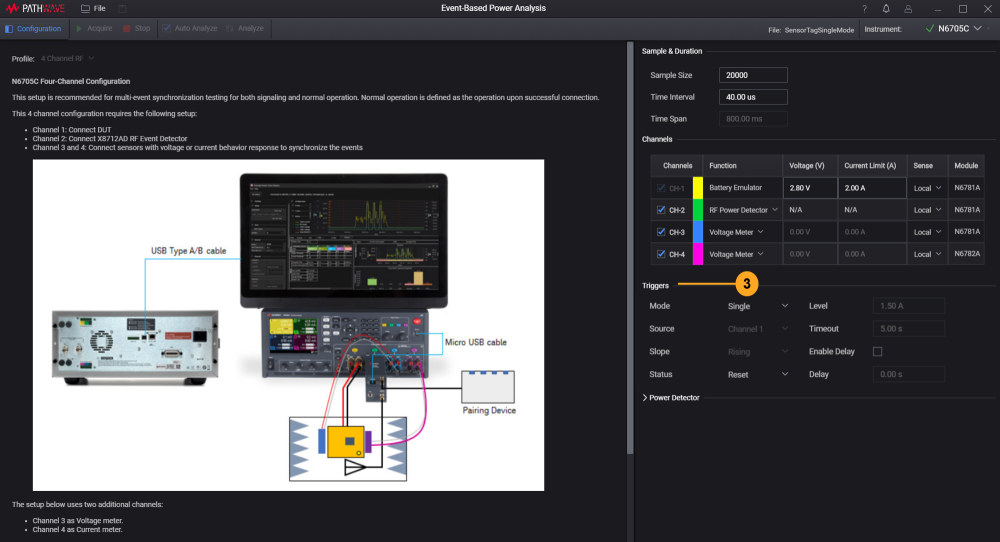
Level: Sets the threshold level that will be displayed on the main chart (red horizontal line) subject to the Source selected. The example below shows the level set at -40 dBm for Channel 2.
|
|
Continuous Mode - Data Logging Capture the waveforms continuously for the duration specified. |
Data File Path: Display the path and the fileName of the .H5 file. The fileName is generated automatically and synced to the Name of the analysis2 file Name. Press Stop Button to Stop Continuous Acquisition check box: Select this check box to enable the use of Stop button to stop the acquisition before the duration ends. Otherwise, you will only be able to wait until the set duration ends. Continuous Acquisition for Duration: Set the duration in (hours):(minutes):(seconds).(milliseconds) for the software to continuously acquire the data. You can still stop the the acquisition using the Stop button.
Note: Selecting the Continuous Mode will disable the Time Span and Sample Size function in Sample and Duration. Based on the value entered in Time Interval, the KS833A2A will compute the following information as defined below:
|

During the data acquisition, the Main Chart will be updated at every 10,000 data points acquired. Subject to the time interval and the duration set for data logging, the software will calculate the number of runs (rounded to the nearest integer) to acquire the 10,000 data points.
Here are two setups to demonstrate the calculation based on a time interval of 409.6 microseconds. The duration to capture 10,000 data points will be 4.096 seconds. You can calculate the number of runs by dividing the duration set with the duration to capture 10,000 data points.
To capture 25 seconds of data, the software is expected to log exactly 6.104 runs of 10,000 data points. For the software can only stop acquiring data at a multiple of 10,000 data points, it will round off to 6 rounds and will only capture up to 24.576 seconds worth of data.
Similarly, the software is expected to perform 6.519 runs of 10,000 data points to capture 26.7 seconds of continuous mode data logging. When rounded to the nearest integer, the software will complete the 7 runs after 28.672 seconds.
The minimum time interval for continuous mode vary subject to the number of active channels selected:
- One Channel: 0.0001024 seconds
- Two Channels: 0.0002048 seconds
- Three Channels: 0.0003072 seconds
- Four Channels: 0.0004096 seconds
Next
According to your test case and requirements, configure the following settings: