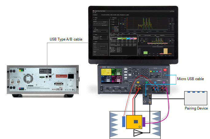
N6705C Four-Channel Configuration
This setup is recommended for multi-event synchronization testing for both signaling and normal operation. Normal operation is defined as the operation upon successful connection.
This four-channel configuration requires the following setup:
- Channel 1: Connect DUT
- Channel 2: Connect X8712AD RF event detector
- Channel 3 and 4: Custom wiring and/or custom sensors with voltage or current response to synchronize the events.
Channel 1 is fixed as 'Battery Emulator' module and is used to power up the DUT and monitor the total current drain.
Channel 2 may use 'Power Detector' module with the X8712AD RF event detector connected to capture the RF signal transmitted or received by the DUT.
-
Follow the instructions from step 1 to 7 in the Connect an Over-the-Air DUT in Self Advertising or Test Mode section.
-
There are two options to set up the connection in Channel 3 and 4:
-
Connect the 2-wire cable to the device subcircuit power lines for events synchronization.
-
Connect to the voltage or current responding sensors without having physical connection to the DUT.
-
-
If you are using a voltage based sensor in Channel 3 and a current based sensor in Channel 4 to synchronize the events, connect your voltage-based sensor to Channel 3 using V+ and V- 2-wire configuration to the output binding post terminals. Do the same to connect the current-based sensor to Channel 4.
You have completed the hardware setup based on this example.
Next step
- To explore other hardware configuration, go to N6705C Two-Channel Configuration or N6705C Two-Channel Configuration for Non-RF Events.
- Go Install the Software to begin setting up the KS833A2A software.