N6705C Two-Channel Configuration for Non-RF Events
The following is a typical setup for non-RF events where it does not involve the use of Channel 2. Use the following software settings:
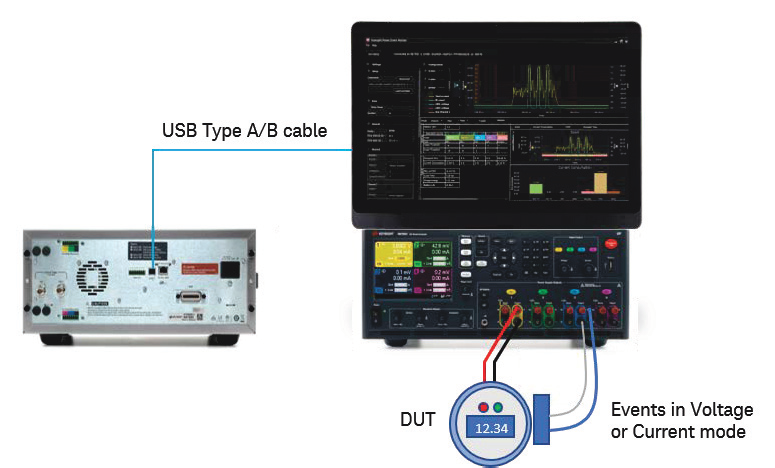
- Channel 1: Battery Emulator for DUT
- Channel 3 or 4: Voltage Meter or Current Meter, according to your choice of sensors
When Channel 3 or 4 is connected to the DUT, the software will use either channel as synchronous events to calculate current consumption.
Follow the instructions below.
-
Refer to N6705C User's Guide for instructions on how to install the N6781A/N6785A SMU modules into the N6705C DC power analyzer.
-
Use the test leads (not included) to connect your DUT to Channel 1 (Battery Emulator).
-
Connect your voltage-based sensor to Channel 3 or 4 using V+ and V- accordingly. Do the same when you are using a current-based sensor.
You have completed the hardware setup based on this example.
Next step
- To explore other hardware configuration, go to N6705C Four-Channel Configuration or N6705C Two-Channel Configuration.
- Go Install the Software to begin setting up the KS833A2A software.