N6705C Two-Channel Configuration
The two-channel configuration is recommended when there is a need to correlate the current consumption waveform with the RF activities of the DUT. You will be able to breakdown the total current consumption according to the key RF events such as when the DUT is transmitting, receiving, processing, idle, or in sleep mode.
There are two typical use cases:
- DUT is set to self advertising or test mode (see Connect an Over-the-Air DUT in Self Advertising or Test Mode).
- DUT is controlled using an external companion device (see Pair an External Companion Device in Signaling Mode).
Channel 1 is fixed as 'Battery Emulator' function and is used to power up the DUT and monitor the total current drain.
Channel 2 is fixed as 'Power Detector' function with the X8712AD RF event detector connected to capture the RF signal transmitted or received by the DUT.
Connect an Over-the-Air DUT in Self Advertising or Test Mode
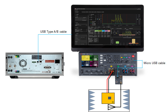
The image above illustrates the typical setup to connect an over-the-air DUT.
-
Refer to N6705C User's Guide for instructions on how to install the N6781A/N6785A SMU modules into the N6705C DC power analyzer.
- Connect the USB Type A/B cable from your PC to the rear panel of N6705C.
-
Connect the Micro-USB cable from the N6705C DC Power Analyzer to the X8712AD RF event detector.
-
Use the test leads (not included) to connect your DUT to the output binding post terminals of Channel 1.
-
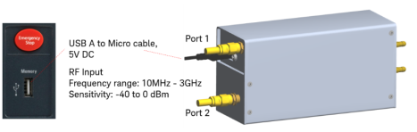
There are two RF ports on the X8712AD. Connect the RF cable (not included) to one of the RF ports and the other end to the back of the shield box. Connect the 50-ohm terminator to the port not in use.
NOTE- The two in one power combiner within the X8712AD produces equal RF signal on port 1 and port 2 on the front panel as shown on X8712AD RF Detector.
- You are recommended to connect the 50-ohm terminator to the unused port to avoid open reflection when you use one of the ports to measure RF power.
- The pass-through loss between port 1 and 2 is approximately 7 to 8 dB.
-
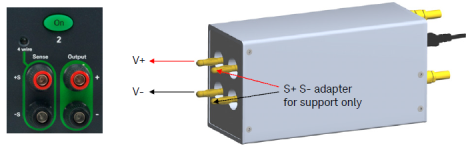
Connect the X8712AD RF Event Detector to Port 2 using V+ and V- 2-wire configuration to receive analog response at the rear banana port as shown below. The output will range from 0 to 2 V.
-
Connect the Micro-USB cable from N6705C to the front panel of X8712AD RF event detector to power the event detector that requires 5 V of DC to operate.
Before you turn on the output, set Channel 2 in Voltage meter (VM) mode in KS833A1B software to prevent generating DC output to the X8712AD RF event detector.
Pair an External Companion Device in Signaling Mode
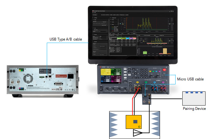
The image above illustrates the typical setup to pair an external companion device in signaling mode.
- Follow the instructions from step 1 to 7 in the Connect an Over-the-Air DUT in Self Advertising or Test Mode section.
-
Connect your companion device to the other front end connector of the X8712AD RF event detector.
NOTEFor sensitivity measurement, the pass-through loss between port 1 and 2 of the X8712AD is approximately 7 to 8 dB.
You have completed the hardware setup based on these examples.
Next step
- To explore other hardware configuration, go to N6705C Four-Channel Configuration or N6705C Two-Channel Configuration for Non-RF Events.
- Go Install the Software to begin setting up the KS833A2A software.